Geomembrane Executive Standard: GB/T17643-2011
Product Introduction
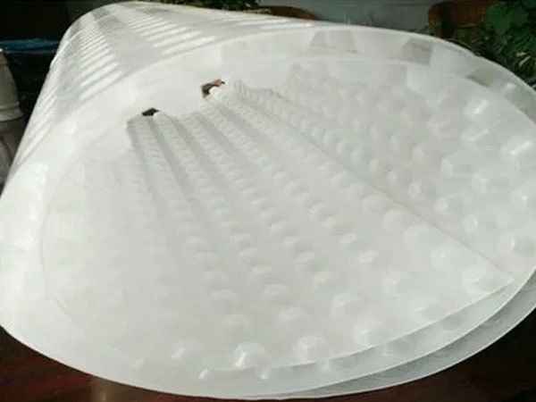
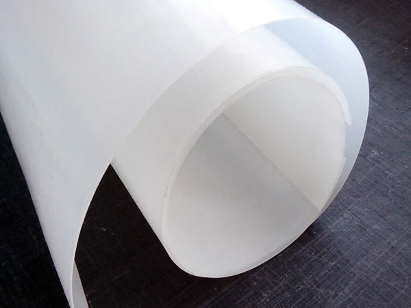
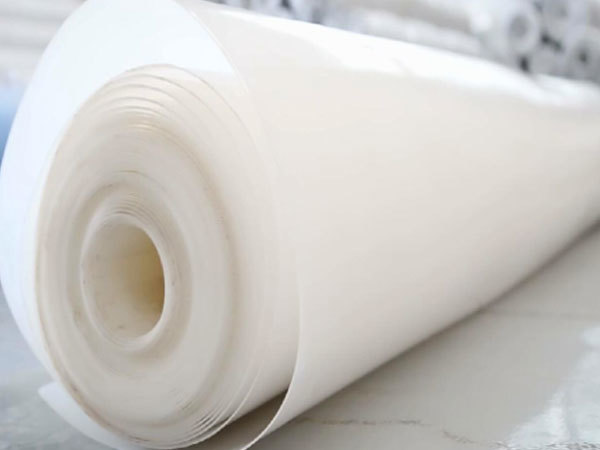
HDPE geomembrane is a plastic coil composed of HDPE, which is a highly crystalline, non-polar thermoplastic resin. The appearance of HDPE in its original state is milky white, with a certain degree of translucency in the micro-thin cross-section. HDPE film has excellent impact resistance, so it is so at room temperature and even at a low temperature of -40F. HDPE film is a polymer non-toxic, tasteless, odorless white granules with a melting point of about 110℃-130℃ and a relative density of 0.918- 0.965; with good heat and cold resistance. Good chemical stability, high rigidity and toughness, good mechanical strength, good resistance to environmental stress cracking and tear strength properties, with the rise in density, mechanical properties and barrier properties will increase accordingly, heat resistance, and tensile strength is also higher; can be resistant to acids, alkalis, organic solvents and other corrosion.
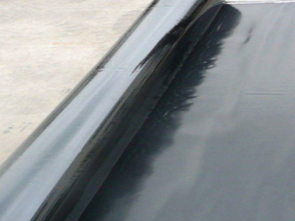
Geomembrane can meet the civil engineering needs of water conservancy, municipal, construction, traffic, subway, tunnel, engineering construction of seepage control, isolation, reinforcement, anti-cracking reinforcement, etc.. It can be used in unconventional temperature environment because it is made of polymer material and the anti-aging agent is added in the production process. It is commonly used for impermeable treatment of dikes, drainage ditches, and anti-fouling treatment of waste sites.
Geomembrane is characterized by high strength, good elongation, large deformation modulus, acid and alkali resistance, corrosion resistance, aging resistance, and good impermeability.
Specification and performance parameters
Glossy high-density polyethylene geomembrane for environmental protection (GH-2S type)
| No. |
Item |
Indicators |
| Thickness mm |
0.30 |
0.50 |
0.75 |
1.00 |
1.25 |
1.50 |
2.00 |
2.50 |
3.00 |
| 1 |
Density g/cm³ |
≥0.940 |
| 2 |
Tensile yield strength (longitudinal and transverse) N/mm |
 |
≥7 |
≥10 |
≥13 |
≥16 |
≥20 |
≥26 |
≥33 |
≥40 |
| 3 |
Tensile breaking strength (longitudinal and transverse) N/mm |
≥6 |
 |
≥15 |
≥20 |
≥25 |
≥30 |
≥40 |
≥50 |
≥60 |
| 4 |
Yield elongation (longitudinal, transverse) % |
|
|
|
≥11 |
| 5 |
Elongation at break (longitudinal, transverse) % |
≥600 |
| 6 |
Right-angle cracking load (longitudinal and transverse) N |
≥34 |
≥56 |
≥84 |
≥115 |
≥140 |
≥170 |
≥225 |
≥280 |
≥340 |
| 7 |
Puncture resistance N |
≥72 |
≥120 |
≥180 |
≥240 |
≥300 |
≥360 |
≥480 |
≥600 |
≥720 |
| 8 |
Carbon black content % |
2.0~3.0 |
| 9 |
Carbon Black Dispersibility |
No more than 1 out of 10 data level 3, level 4 and 5 are not allowed |
| No. |
Item |
Indicators |
| Thickness mm |
0.30 |
0.50 |
0.75 |
1.00 |
1.25 |
1.50 |
2.00 |
2.50 |
3.00 |
| 10 |
Oxidation induction time (OIT) min |
≥60 |
| 11 |
Low moisture impact embrittlement performance |
By |
| 12 |
Water vapor permeability coefficient
g ·cm/(cm² ·s ·Pa) |
≤1.0×10⁻¹³ |
| 13 |
Dimensional stability % |
±2.0 |
| Note; The technical performance index requirements for thickness specifications not listed in the table are implemented in accordance with the interpolation method. |
Low-density polyethylene geomembrane (GL-1 type)
| No. |
Item |
Indicators |
| Thickness mm |
0.75 |
1.00 |
1.25 |
1.50 |
2.00 |
2.50 |
3.00 |
| 1 |
Density g/cm³ |
≥0.940 |
| 2 |
Tensile yield strength (longitudinal and transverse) N/mm |
≥11 |
≥15 |
≥18 |
≥22 |
≥29 |
≥37 |
≥44 |
| 3 |
Tensile breaking strength (longitudinal and transverse) N/mm |
≥20 |
≥27 |
≥33 |
≥40 |
≥53 |
≥67 |
≥80 |
| 4 |
Yield elongation (longitudinal, transverse) % |
≥12 |
| 5 |
Elongation at break (longitudinal, transverse) % |
≥700 |
| 6 |
Right-angle cracking load (longitudinal and transverse) N |
≥93 |
≥125 |
≥160 |
≥190 |
≥250 |
≥315 |
≥375 |
| 7 |
Puncture resistance N |
≥240 |
≥320 |
≥400 |
≥480 |
≥640 |
≥800 |
≥960 |
| 8 |
Tensile load stress cracking (notched constant load tension method) h |
|
≥300 |
| 9 |
Carbon black content % |
2.0~3.0 |
| No. |
Item |
Indicators |
| Thickness mm |
0.75 |
1.00 |
1.25 |
1.50 |
2.00 |
2.50 |
3.00 |
| 10 |
Carbon Black Dispersibility |
No more than 1 out of 10 data level 3, level 4 and 5 are not allowed |
| 11* |
Oxidation Induction Time (OIT) at atmospheric pressure |
Atmospheric pressure oxidation induction time ≥ 100 |
| High pressure oxidation induction time ≥ 400 |
| 12 |
Thermal aging at 85 ℃ (OIT retention at atmospheric pressure after 90 d) % |
≥55 |
| 13* |
UV resistance (OIT retention after 1600 h UV irradiation) % |
≥50 |
| Note; The technical performance index requirements for thickness specifications not listed in the table are implemented in accordance with the interpolation method. |
| 11, 13 two indicators of atmospheric pressure OIT (retention rate) and high pressure OIT (retention rate) can choose either test. |
Linear low-density polyethylene geomembrane for environmental protection (GL-2 type)
| No. |
Item |
Indicators |
| Thickness mm |
0.30 |
0.50 |
0.75 |
1.00 |
1.25 |
1.50 |
2.00 |
2.50 |
3.00 |
| 1 |
Density g/cm³ |
<0.939 |
| 2 |
Tensile breaking strength (longitudinal and transverse) N/mm |
≥6 |
≥9 |
≥14 |
≥19 |
≥23 |
≥28 |
≥37 |
≥47 |
≥56 |
| 3 |
Elongation at break (longitudinal, transverse) % |
≥560 |
| 4 |
Right-angle cracking load (longitudinal and transverse) N |
≥27 |
≥45 |
≥63 |
≥90 |
≥108 |
≥135 |
≥180 |
≥225 |
≥270 |
| 5 |
Puncture resistance N |
≥52 |
≥84 |
≥135 |
≥175 |
≥220 |
≥260 |
≥350 |
≥435 |
2525 |
| 6* |
Carbon black content % |
2.0~3.0 |
| 7* |
Carbon Black Dispersibility |
No more than 1 out of 10 data level 3, level 4 and 5 are not allowed |
| No. |
Item |
Indicators |
| Thickness mm |
0.30 |
0.50 |
0.75 |
1.00 |
1.25 |
1.50 |
2.00 |
2.50 |
3.00 |
| 8 |
Oxidation Induction Time (OIT) at atmospheric pressure |
≥60 |
| 9 |
Low temperature impact embrittlement properties |
By |
| 10 |
Water vapor permeability coefficient
g ·cm/(cm³ ·s ·Pa) |
≤1.0×10⁻¹ |
| 11 |
Dimensional stability % |
士2.0 |
| Note; The technical performance index requirements for thickness specifications not listed in the table are implemented in accordance with the interpolation method. |
| 6, 7 two indicators are only applicable to black geomembrane. |
Linear low-density polyethylene geomembrane for environmental protection (GL-2 type)
| No. |
Item |
Indicators |
| Thickness mm |
0.50 |
0.75 |
1.00 |
1.25 |
1.50 |
2.00 |
2.50 |
3.00 |
| 1 |
Density g/cm³ |
≤0.939 |
| 2 |
Tensile breaking strength (longitudinal and transverse) N/mm |
≥13 |
≥20 |
≥27 |
≥33 |
≥40 |
253 |
≥66 |
≥80 |
| 3 |
Elongation at break (longitudinal, transverse) % |
≥800 |
| 4 |
2% positive cutting modulus N/mm |
≤210 |
≤370 |
≤420 |
≤520 |
≤630 |
≤840 |
≤1050 |
≤1260 |
| 5 |
Right-angle cracking load (longitudinal and transverse) N |
≥50 |
≥70 |
≥100 |
≥120 |
≥150 |
≥200 |
≥250 |
≥300 |
| 6 |
Puncture resistance N |
≥120 |
≥190 |
≥250 |
≥310 |
≥370 |
≥500 |
≥620 |
≥750 |
| 7 |
Carbon black content % |
2.0~3.0 |
| 8 |
Carbon Black Dispersibility |
No more than 1 out of 10 data level 3, level 4 and 5 are not allowed |
| 9* |
Oxidation induction time (OIT) min |
Atmospheric pressure oxidation induction time ≥ 100 |
| High pressure oxidation induction time ≥ 400 |
| 10 |
Thermal aging at 85 ℃ (OIT retention at atmospheric pressure after 90 d) % |
≥35 |
| 11* |
UV resistance (OIT retention after 1600 h UV irradiation) % |
≥35 |
| Note; The technical performance index requirements for thickness specifications not listed in the table are implemented in accordance with the interpolation method. |
| 9, 11 two indicators of atmospheric pressure OIT (retention rate) and high pressure OIT (retention rate) can choose either test. |


