


NEWS
A large private enterprise specializing in the production and operation of geotechnical materials
02
2019
-
03
Analysis on Construction Technology and Flow Control of Secondary Lining of Tunnel
Author:
Tunnel secondary lining construction technology and process control.
I. Construction Technology
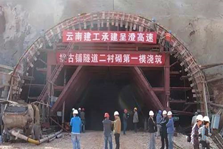
Secondary lining is carried out after the deformation of surrounding rock and initial support is basically stable according to the measured conditions, and the safe distance between excavation and lining can be met by appropriately following the excavation face. The second lining is transported to the construction site by a 12m formwork trolley, and the concrete is transported to the construction site by a concrete truck and pumped into the formwork. The concrete adopts the attached vibrator as the main and inserting vibrator as the auxiliary vibrating mode. In the reinforced concrete lining section, the reinforcement bar is processed and formed outside the tunnel, and the multi-functional working bench is installed inside the tunnel.
II. Construction process
1. Manufacturing and Installation of Reinforcement Bars
The main reinforcement and stirrups of lining are processed by the steel bar processing plant. The processing and manufacturing technology of the steel bar should meet the requirements of design and specification.
In order to ensure the accurate positioning of the secondary lining steel bar, the thickness of the protective layer of the steel bar meets the requirements. Specific practices:
Firstly, the surveyors set out the center points of the two steel bars in the leveling layer and vault waterproof cloth with coordinates to determine the normal direction and ensure the verticality of the positioning steel bars and the accuracy of the connection with the reserved steel bars in inverted arch. The perpendicularity of steel bar binding is determined by three-point hanging ball method.
(2) Measuring the elevation of the center point of the steel bar on the filling surface of inverted arch with the level, calculating the elevation difference between the center of the circle at the mileage and the center point of the inverted arch filling, and using the self-made triangle frame to determine the position of the center of the circle.
(3) After the center of the circle is determined, the size of the positioning steel bar is checked by the method of ruler, and the position of the positioning steel bar is adjusted again to meet the design requirements, and the steel bar is fixed after all meeting the requirements. The steel bar fixing is controlled by adjustable support rod welded by steel pipe on self-made trolley.
(4) After fixing the positioning reinforcement bar, according to the designed spacing of reinforcement bar, the position of the circumferential main reinforcement bar is marked with chalk, and the installation position of the longitudinal distribution reinforcement bar is marked on the positioning reinforcement bar, and then the reinforcement bar in this section is tied. All reinforcing bars should be tied at the intersection.
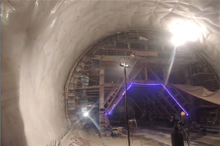
2. Location of the second liner trolley
The trolley track adopts heavy rail, and the bottom is directly placed on the concrete surface filled with the inverted arch to ensure the stability of the trolley. The control standard of track layout is that the distance between track centers is 6m, and the allowable error is (+25px); the second is that the elevation of track surface is 375px above the center of tunnel filling surface, and the allowable error is (+25px). The center line of the formwork should be adjusted to coincide with the center of the main beam of the trolley as far as possible so that the trolley is in a good stress state during the concrete pouring process.
The change of overlap length between left and right sides caused by the difference of arc length between inside and outside should be taken into account in the positioning of trolley in curve section so as to make the arc rounded and reduce the staggered joint platform.
The trolley runs to the position of the vertical die, adjusts to the exact position with the lateral jack, and carries on the positioning re-examination until it is adjusted to the exact position. When the trolley is in place, check whether the connection of each node of the trolley is firm and whether there is any displacement. Five-point positioning method is used to check whether the formwork is warped or twisted, and whether the position is accurate, so as to ensure lining clearance, and at the same time, it is easy to overcome the staggered platform at the lining ring joint. In order to avoid floating on the trolley when pouring side wall concrete, wooden braces or jacks should be installed on the top of the trolley. At the same time, check whether the working window is in good condition. When measuring the setting-out, the reserved sinking amount should be considered.
3. Treatment of Construction Joints and Deformation Joints
The composite waterproofing structure of the middle-buried rubber water-stop belt and the back-mounted water-stop belt is set in the circumferential construction joint of the tunnel in this bid section. The composite waterproofing structure of the middle-buried steel-edge rubber water-stop belt and the expanded rubber water-stop strip is adopted in the longitudinal construction joint. During construction, the water stop belt is installed in the center of the plug template of the lining trolley, and fixed by U-shaped clamp to ensure that the position of the water stop belt is installed accurately. Waterproofing drawings of ring and longitudinal construction joints are shown in Fig. 1-2.

The construction joints shall be smooth, straight, clean and without seepage on both sides. The cement mortar and soft layer on the surface of concrete should be chiseled out in construction joints. Chiseling makes the exposed area of fresh concrete not less than 75%.
The deformation joints of the tunnel in this section are located at the significant change of stratum, the demarcation of light and shade and the obvious change of cross section. The deformation joints are made of composite waterproofing structures with rubber waterproofing belts, external waterproofing belts and seam materials. The waterproofing schematic drawings of the deformation joints are shown in Fig. 1-3.
5. Key Points of Quality Control
1. Quality control measures
(1) The construction of lining shall be under the overall responsibility of the manager of the work area, with the supervisor and the squad leader. Another quality inspection engineer and test engineer are set up for quality control.
(2) Strictly follow the technical undertaking construction, strictly abide by the construction specifications, and strictly grasp the construction technology standards, quality inspection and acceptance standards. Rework if it fails to meet the requirements and hold the responsible person accountable.
(3) Technical submission must be made before each working procedure is constructed, working procedures, quality requirements and standards must be clearly defined to the constructors, and quality control must be strictly controlled, and the technical personnel shall be responsible for it.
(4) Insist on the three-level surveying review system. Construction surveying layout should be checked repeatedly to ensure that the midline, horizontal and structural dimensions and positions are correct. The Surveying Engineer is responsible for it.
(5) Strictly implement the on-site duty system to solve problems arising in construction in a timely manner.
(6) To ensure that the structural dimension meets the design requirements, the duty personnel, the Surveying Engineer and the quality inspection engineer shall be responsible for it.
(7) The Test Engineer shall be responsible for the test and inspection of various materials.
(8) If construction is strictly in accordance with the construction specifications and quality problems are caused by non-conformity with the specifications, the quality inspection engineer shall have the right of veto on quality and shall have the right to order him to stop work and rectify until the requirements are met.
(9) Strict implementation of the three-level inspection system, first self-inspection by the work class, qualified and then submitted to the quality inspection engineer for inspection and acceptance by the supervision engineer.
(10) Strictly control the footage of the face. The distance between the secondary lining and the face of the face should not be greater than 90 m for grade IV surrounding rock and 70 m for grade V surrounding rock.
(11) Measures to Eliminate Misalignment of Concrete Joints
(1) Eliminate the ring joint staggered platform: First, before the trolley is in place, the concrete overlap part and the surface of the overlap part of the trolley (including the arch toe part on the top of the middle wall) are thoroughly cleaned, so that the trolley and the concrete surface are as close as possible; Second, to strengthen the trolley support, all the support should be in place to ensure the overall force of the trolley, and if necessary, to add screw support at the end of the trolley; The front end of the trolley is supported to prevent the floating of the trolley from causing the arch staggering; the fourth is to strictly control the speed of concrete pouring (generally controlled for about 4 hours) and slump (generally 350 px) above the bottom of the trolley; the fifth is to inspect the size of the front and rear sections of the trolley and eliminate them in time; the sixth is to accurately control the middle line of the trolley on the same plane as the middle line of the tunnel; and the seventh is to maintain the middle line of the trolley. The overlap length between the trolley and the concrete is 10 centimeters.
(2) Eliminate the staggered platform of trolley formwork: weld the joints of formwork plates and grind the welds flat to form three large formwork (i.e. one arch and one left and right side wall), so as to restrain the warping deformation of formwork and affect the surface quality of concrete in the course of using, so as to overcome the staggered platform of the joints between plates.
(3) Misalignment and leakage of operation window of control trolley: before closing operation window, the remnants of concrete slurry in window frame must be cleaned up, and the clamping clamp must be locked after wiping with wet rag, and the closing fulcrum should be tightened with wedge-shaped wooden stopper to prevent uneven patches or even leakage on the concrete surface of window due to inadequate closure of operation window.
(12) In order to reduce the surface bubbles and improve the appearance quality of concrete in the back-arc section of the second lining, it is necessary to mix water reducing agent and fly ash to improve the performance of concrete, control the slump of concrete (350px), and tamping method. The three methods are used synthetically to reduce the air bubbles in the back arc section and improve the surface quality of lining concrete effectively.
(13) Modification and Dismantling of Concrete Appearance Defects
After the mould, if defects are found, they shall not be repaired without authorization, and shall be studied jointly by technicians and handled promptly with the approval of the supervising engineer.
Bubble: After mixing white cement and ordinary cement according to the proportion determined by the contrast test of lining surface color, local filling and smoothing is done.
Circumferential joint treatment: using radial ruler to draw lines, cutting machine to cut seams, seam depth is about 50px, irregular parts are partially repaired or polished by grinding wheel machine, modified with high-grade cement mortar, and smoothed with steel trowel to make construction seams round and neat.
For surface color inconsistency, sandpaper is used repeatedly to wipe several times.
The surrounding of the reserved cavern should be cleaned up first, then sprayed wet, using high-grade mortar with the same color as the second lining, smoothing and calendering.
2. Quality acceptance
(1) The allowable deviation and inspection method of lining formwork installation are shown in Table 2-1, and the allowable deviation and inspection method of embedded parts and reserved holes are shown in Table 2-2.

undefined

Large private enterprises that produce and operate geotechnical materials
Online Message

Contact us
Address:Tai’an City high-tech zone longteng road taishan base industry east
Tel:0086-538-8481118
Mobile:+86-15053890323
Fax:0086-538-8481118
Email:lucas@bpmaterial.com
Copyright © Desheng Synthetic Materials Co., Ltd.